CONSTRUCTION OF THE CHAIN
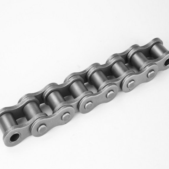
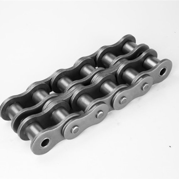
Two different sizes of roller chain, showing construction.
There are two types of links alternating in the bush roller chain. The first type is inner links, having two inner plates held together by two sleeves or bushings upon which rotate two rollers. Inner links alternate with the second type, the outer links, consisting of two outer plates held together by pins passing through the bushings of the inner links. The "bushingless" roller chain is similar in operation though not in construction; instead of separate bushings or sleeves holding the inner plates together, the plate has a tube stamped into it protruding from the hole which serves the same purpose. This has the advantage of removing one step in assembly of the chain.
The roller chain design reduces friction compared to simpler designs, resulting in higher efficiency and less wear. The original power transmission chain varieties lacked rollers and bushings, with both the inner and outer plates held by pins which directly contacted the sprocket teeth; however this configuration exhibited extremely rapid wear of both the sprocket teeth, and the plates where they pivoted on the pins. This problem was partially solved by the development of bushed chains, with the pins holding the outer plates passing through bushings or sleeves connecting the inner plates. This distributed the wear over a greater area; however the teeth of the sprockets still wore more rapidly than is desirable, from the sliding friction against the bushings. The addition of rollers surrounding the bushing sleeves of the chain and provided rolling contact with the teeth of the sprockets resulting in excellent resistance to wear of both sprockets and chain as well. There is even very low friction, as long as the chain is sufficiently lubricated. Continuous, clean, lubrication of roller chains is of primary importance for efficient operation as well as correct tensioning.
LUBRICATION
Many driving chains (for example, in factory equipment, or driving a camshaft inside an internal combustion engine) operate in clean environments, and thus the wearing surfaces (that is, the pins and bushings) are safe from precipitation and airborne grit, many even in a sealed environment such as an oil bath. Some roller chains are designed to have o-rings built into the space between the outside link plate and the inside roller link plates. Chain manufacturers began to include this feature in 1971 after the application was invented by Joseph Montano while working for Whitney Chain of Hartford, Connecticut. O-rings were included as a way to improve lubrication to the links of power transmission chains, a service that is vitally important to extending their working life. These rubber fixtures form a barrier that holds factory applied lubricating grease inside the pin and bushing wear areas. Further, the rubber o-rings prevent dirt and other contaminants from entering inside the chain linkages, where such particles would otherwise cause significant wear.[citation needed]
There are also many chains that have to operate in dirty conditions, and for size or operational reasons cannot be sealed. Examples include chains on farm equipment, bicycles, and chain saws. These chains will necessarily have relatively high rates of wear, particularly when the operators are prepared to accept more friction, less efficiency, more noise and more frequent replacement as they neglect lubrication and adjustment.
Many oil-based lubricants attract dirt and other particles, eventually forming an abrasive paste that will compound wear on chains. This problem can be circumvented by use of a "dry" PTFE spray, which forms a solid film after application and repels both particles and moisture.
VARIANTS DESIGN
Layout of a roller chain: 1. Outer plate, 2. Inner plate, 3. Pin, 4. Bushing, 5. Roller
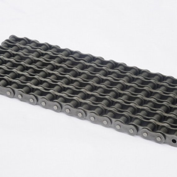
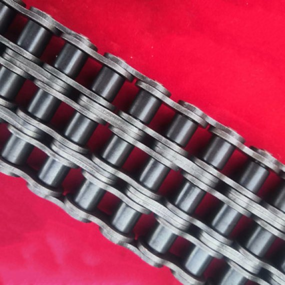
If the chain is not being used for a high wear application (for instance if it is just transmitting motion from a hand-operated lever to a control shaft on a machine, or a sliding door on an oven), then one of the simpler types of chain may still be used. Conversely, where extra strength but the smooth drive of a smaller pitch is required, the chain may be "siamesed"; instead of just two rows of plates on the outer sides of the chain, there may be three ("duplex"), four ("triplex"), or more rows of plates running parallel, with bushings and rollers between each adjacent pair, and the same number of rows of teeth running in parallel on the sprockets to match. Timing chains on automotive engines, for example, typically have multiple rows of plates called strands.
Roller chain is made in several sizes, the most common American National Standards Institute (ANSI) standards being 40, 50, 60, and 80. The first digit(s) indicate the pitch of the chain in eighths of an inch, with the last digit being 0 for standard chain, 1 for lightweight chain, and 5 for bushed chain with no rollers. Thus, a chain with half-inch pitch would be a #40 while a #160 sprocket would have teeth spaced 2 inches apart, etc. Metric pitches are expressed in sixteenths of an inch; thus a metric #8 chain (08B-1) would be equivalent to an ANSI #40. Most roller chain is made from plain carbon or alloy steel, but stainless steel is used in food processing machinery or other places where lubrication is a problem, and nylon or brass are occasionally seen for the same reason.
Roller chain is ordinarily hooked up using a master link (also known as a connecting link), which typically has one pin held by a horseshoe clip rather than friction fit, allowing it to be inserted or removed with simple tools. Chain with a removable link or pin is also known as cottered chain, which allows the length of the chain to be adjusted. Half links (also known as offsets) are available and are used to increase the length of the chain by a single roller. Riveted roller chain has the master link (also known as a connecting link) "riveted" or mashed on the ends. These pins are made to be durable and are not removable.
CHAIN STRENGTH
The most common measure of roller chain's strength is tensile strength. Tensile strength represents how much load a chain can withstand under a one-time load before breaking. Just as important as tensile strength is a chain's fatigue strength. The critical factors in a chain's fatigue strength is the quality of steel used to manufacture the chain, the heat treatment of the chain components, the quality of the pitch hole fabrication of the linkplates, and the type of shot plus the intensity of shot peen coverage on the linkplates. Other factors can include the thickness of the linkplates and the design (contour) of the linkplates. The rule of thumb for roller chain operating on a continuous drive is for the chain load to not exceed a mere 1/6 or 1/9 of the chain's tensile strength, depending on the type of master links used (press-fit vs. slip-fit)[citation needed]. Roller chains operating on a continuous drive beyond these thresholds can and typically do fail prematurely via linkplate fatigue failure.
The standard minimum ultimate strength of the ANSI 29.1 steel chain is 12,500 x (pitch, in inches)2. X-ring and O-Ring chains greatly decrease wear by means of internal lubricants, increasing chain life. The internal lubrication is inserted by means of a vacuum when riveting the chain together.